CCNA Network protocols
February 10, 2017
Friday 10 February 2017
CCNA Network protocols
February 10, 2017
ICMP (Internet Control Message Protocol)
ICMP (Internet Control Message Protocol)
ICMP (Internet Control Message Protocol) is a network layer protocol that reports errors and provides information related to IP packet processing. ICMP is used by network devices to send error messages indicating, for example, that a requested service is not available or that a host isn’t reachable.ICMP is commonly used by network tools such as ping or traceroute. Consider the following example that illustrates how ping can be used to test the reachability of a host:
")
CCNA Network protocols
February 10, 2017
APIPA (Automatic Private IP Addressing)
APIPA (Automatic Private IP Addressing)
Automatic Private IP Addressing (APIPA) is a feature in Windows operating systems that enables computers to automatically self-configure an IP address and subnet mask when their DHCP server isn’t reachable. The IP address range for APIPA is 169.254.0.1-169.254.255.254, with the subnet mask of 255.255.0.0.
CCNA Network protocols
February 10, 2017
NTP (Network Time Protocol)
NTP (Network Time Protocol)
Network Time Protocol (NTP) is an application layer protocol used for clock synchronization between hosts on a TCP/IP network. The goal of NTP is to ensure that all computers on a network agree on the time, since even a small difference can create problems. For example, if there is more than 5 minutes difference on your host and the Active Directory domain controller, you will not be able to login into your AD domain.NTP uses a hierarchical system of time sources. At the top of the structure are highly accurate time sources – typically atomic or GPS clocks. These clocks are known as stratum 0 servers. Stratum 1 servers are directly linked to stratum 0 servers and computers run NTP servers that deliver the time to stratum 2 servers, and so on (image source: Wikipedia):
CCNA Network protocols
February 10, 2017
HTTP & HTTPS
HTTP & HTTPS
HTTP (Hypertext Transfer Protocol)
HTTP
is an client-server protocol that allows clients to request web pages
from web servers. It is an application level protocol widely used on the
Internet. Clients are usually web browsers. When a user wants to access
a web page, a browser sends an HTTP Request message to the web server.
The server responds with the requested web page. Web servers usually use
TCP port 80.
CCNA Network protocols
February 10, 2017
SNMP (Simple Network Management Protocol)
SNMP (Simple Network Management Protocol)
Simple Network Management Protocol (SNMP) is an application layer protocol that is used for network device management. This protocol can collects and manipulate valuable network information from switches, routers, servers, printers, and other network-attached devices.An SNMP-managed network consists of two components:
CCNA Network protocols
February 10, 2017
FTP & TFTP
FTP & TFTP
FTP (File Transfer Protocol)
FTP
is a network protocol used to transfer files from one computer to
another over a TCP network. Like Telnet, it uses a client-network
arhitecture, which means that a user has to have an FTP client installed
to access an FTP server running on the remote machine. After
establishing an FTP connection, the user can download or upload files to
and from the FTP server.
CCNA Network protocols
February 10, 2017
Telnet & SSH
Telnet & SSH
Telnet
Telnet
is a network protocol that allows a user to communicate with a remote
device. It is a virtual terminal protocol used mostly by network
administrators to remotely access and manage devices. Administrator can
access the device by “telnetting” to the IP address or hostname of a
remote device.
CCNA Network protocols
February 10, 2017
DHCP & DNS
DHCP & DNS
DHCP (Dynamic Host Configuration Protocol)
DHCP
is a network protocol that is used to assign various network parameters
to a device. This greatly simplifies administration, since there is no
need to assign static network parameters for each device separately.
DHCP is a client-server protocol. A client is a device that is
configured to use DHCP to request network parameters from a DHCP server.
DHCP server maintains a pool of available IP addresses and assignes one
of them to the host. A DHCP server can also provide some other
parameters, such as:
• subnet mask
• default gateway
• domain name
• DNS server
• subnet mask
• default gateway
• domain name
• DNS server
Tuesday 7 February 2017
CCNA Network protocols
February 07, 2017
ARP
ARP
ARP
(Address Resolution Protocol) is a network protocol used to find out
the hardware (MAC) address of a device from an IP address. It is used
when a device wants to communicate with some other device on a local
network (for example on an Ethernet network that requires physical
addresses to be known before sending packets). The sending device uses
ARP to translate IP addresses to MAC addresses. The device sends an ARP
request message containing the IP address of the receiving device. All
devices on a local network segment see the message, but only the device
that has that IP address responds with the ARP reply message containing
its MAC address. The sending device now has enough information to send
the packet to the receiving device.
CCNA Network protocols
February 07, 2017
Ports explained
Ports explained
A port is a 16-bit number used to identify specific applications and services. TCP and UDP specify the source and destination port numbers in their packet headers and that information, along with the source and destination IP addresses and the transport protocol (TCP or UDP), enables applications running on hosts on a TCP/IP network to communicate.Applications that provide a service (such as FTP or and HTTP servers) open a port on the local computer and listen for connection requests. A client can request the service by pointing the request to the application’s IP address and port. A client can use any locally unused port number for communication. Consider the following example:
CCNA Network protocols
February 07, 2017
UDP explained
UDP explained
One other important protocol in the TCP/IP site is User Datagram Protocol (UDP). This protocol is basically a scaled-down version of TCP. Just like TCP, this protocol provides delivery of data between applications running on hosts on a TCP/IP network, but, unlike TCP, it does not sequence the data and does not care about the order in which the segments arrive at the destination. Because of this it is considered to be an unreliable protocol. UDP is also considered to be a connectionless protocol, since no virtual circuit is established between two endpoints before the data transfer takes place.
CCNA Network protocols
February 07, 2017
TCP explained
TCP explained
One of the main protocols in the TCP/IP suite is Transmission Control Protocol (TCP). TCP provides reliable and ordered delivery of data between applications running on hosts on a TCP/IP network. Because of its reliable nature, TCP is used by applications that require high reliability, such as FTP, SSH, SMTP, HTTP, etc.
CCNA Network protocols
February 07, 2017
TCP/IP suite of protocols
TCP/IP suite of protocols
The TCP/IP suite is a set of protocols used on computer networks today (most notably on the Internet). It provides an end-to-end connectivity by specifying how data should be packetized, addressed, transmitted, routed and received on a TCP/IP network. This functionality is organized into four abstraction layers and each protocol in the suite resides in a particular layer.
The TCP/IP suite is named after its most important protocols, the Transmission Control Protocol (TCP) and the Internet Protocol (IP). Some of the protocols included in the TCP/IP suite are:
- ARP (Address Resolution Protocol) – used to convert an IP address to a MAC address.
- IP (Internet Protocol) – used to deliver packets from the source host to the destination host based on the IP addresses.
- ICMP (Internet Control Message Protocol) – used to detects and reports network error conditions. Used in ping.
- TCP (Transmission Control Protocol) – a connection-oriented protocol that enables reliable data transfer between two computers.
- UDP (User Datagram Protocol) – a connectionless protocol for data transfer. Since a session is not created before the data transfer, there is no guarantee of data delivery.
- FTP (File Transfer Protocol) – used for file transfers from one host to another.
- Telnet (Telecommunications Network) – used to connect and issue commands on a remote computer.
- DNS (Domain Name System) – used for host names to the IP address resolution.
- HTTP (Hypertext Transfer Protocol) – used to transfer files (text, graphic images, sound, video, and other multimedia files) on the World Wide Web.
The following table shows which protocols reside on which layer of the TCP/IP model:

CCNA Network tools
February 07, 2017
Traceroute
Traceroute
Traceroute
is a CLI (Command-line interface)-based tool used to identify the path
used by a packet to reach its target. This tool also uses ICMP messages,
but unlike ping, identifies every router in a path. Traceroute is
useful when troubleshooting network problems because it can help
identify where exactly the problem is.
Traceroute
sends a series of ICMP echo request packets to a destination. First
series of messages has a Time to Live (TTL) parameter set to 1, which
means that the first router in a path will discard the packet and send
an ICMP Time Exceeded message. TTL is then increased by one until the
destination host is reached and an ICMP echo reply message is received.
Originating host can then use received ICMP messages to identify all
routers in a path.
The traceroute command on Windows is named tracert. On Unix and Cisco IOS traceroute it is invoked using the traceroute command.
Here is an example showing the tracert command in Windows:

Traceroute on Unix-like operating systems
Traceroute
command on Unix works slighty different than the Windows version. It
uses UDP packets with a large destination port number (33434 to 33534)
that is unlikely to be used by any application at the destination host.
Like the Windows version of the command, traceroute on Unix uses TTL to
get the IP addresses of the intermediary routers. When a destination
host is reached, it replies with an ICMP port unreachable message.
CCNA Network tools
February 07, 2017
Ping
Ping
A
ping is perhaps the most commonly used tool when troubleshooting a
network. Ping (Packet Internet Groper) tool is included with most
operating systems. It is invoked using a ping command. Ping command uses
ICMP (Internet Control Message Protocol). Ping works by sending an ICMP
echo request message to the specified IP address. If the computer with
the destination IP address is reachable, it responds with an ICMP echo
reply message.
A
ping command usually outputs some other information about a network
performance, e.g. a round-trip time, a time to send an ICMP request
packetand receive an ICMP reply packet.
Here is an output of the ping command from Windows 7:

In
the example above we have pinged the ip address 10.10.100.1. By
default, ping on Windows sends four ICMP request packets. As you can see
from the output above, the host with the IP address of 10.10.100.1 is
reachable and has replied with four ICMP reply packets. You can also see
that the remote host has replied within 1 ms, which indicates that the
network is not congested.
Monday 6 February 2017
CCNA IP addresses
February 06, 2017
Create subnets
Create subnets
There are a couple of ways to create subnets. In this article we will subnet a class C address 192.168.0.0 that, by default, has 24 subnet bits and 8 host bits.Before we start subnetting, we have to ask ourselves these two questions:
1. How many subnets do we need?
2x = number of subnets. x is the number of 1s in the subnet mask. With 1 subnet bit, we can have 21 or 2 subnets. With 2 bits, 22 or 4 subnets, with 3 bits, 23 or 8 subnets, etc.
2. How many hosts per subnet do we need?
2y – 2 = number of hosts per subnet. y is the number of 0s in the subnet mask.
An example will help you understand the subnetting concept. Let’s say that we need to subnet a class C address 192.168.0.0/24. We need two subnets with 50 hosts per subnet. Here is our calculation:
1. Since we need only two subnets, we need 21 subnet bits. In our case, this means that we will take one bit from the host part. Here is the calculation:
First, we have a class C address 192.168.0.0 with the subnet mask of 24. Let’s convert them to binary:
192.168.0.0 = 11000000.10101000.00000000.00000000
255.255.255.0 = 11111111.11111111.11111111.00000000
We need to take covert a single zero from the host part of the subnet mask. Here is our new subnet mask:
255.255.255.128 = 11111111.11111111.11111111.10000000
Remember, the ones in the subnet mask represent the network.
2. We need 50 hosts per subnet. Since we took one bit from the host part, we are left with seven bits for the hosts. Is it enough for 50 hosts? The formula to calculate the number of hosts is 2y – 2, with y representing the number of host bits. Since 27 – 2 is 126, we have more than enough bits for our hosts.
3. Our network will look like this:
192.168.0.0/25 – the first subnet has the subnet number of 192.168.0.0. The range of IP addresses in this subnet is 192.168.0.0 – 192.168.0.127.
192.168.0.128/25 – the second subnet has the subnet number of 192.168.0.128. The range of IP addresses in this subnet is 192.168.0.128 – 192.168.0.255.
CCNA IP addresses
February 06, 2017
Subnet mask
Subnet mask
An
IP address is divided into two parts: network and host parts. For
example, an IP class A address consists of 8 bits identifying the
network and 24 bits identifying the host. This is because the default
subnet mask for a class A IP address is 8 bits long. (or, written in
dotted decimal notation, 255.0.0.0). What does it mean? Well, like an IP
address, a subnet mask also consists of 32 bits. Computers use it to
determine the network part and the host part of an address. The 1s in
the subnet mask represent a network part, the 0s a host part.
Computers works only with bits. The math used to determine a network range is binary AND.

Let’s say that we have the IP address of 10.0.0.1 with the default subnet mask of 8 bits (255.0.0.0).
First, we need to convert the IP address to binary:
IP address: 10.0.0.1 = 00001010.00000000.00000000.00000001
Subnet mask 255.0.0.0 = 11111111.00000000.00000000.0000000
Subnet mask 255.0.0.0 = 11111111.00000000.00000000.0000000
Computers then use the AND operation to determine the network number:

The
computer can then determine the size of the network. Only IP addresses
that begins with 10 will be in the same network. So, in this case, the
range of addresses in this network is 10.0.0.0 – 10.255.255.255.
NOTE – A subnet mask must always be a series of 1s followed by a series of 0s.
CCNA IP addresses
February 06, 2017
Subnetting explained
Subnetting explained
Subnetting is the practice of dividing a network into two or more smaller networks. It increases routing efficiency, enhances the security of the network and reduces the size of the broadcast domain.Consider the following example:

a single broadcast domain – all hosts are in the same broadcast domain. A broadcast sent by a device on the network will be processed by all hosts.
network security – each device can reach any other device on the subnet, which can present security problems.
organizational problems – in a large networks, different departments are usually grouped into different subnets. For example, you can group all devices from the Accounting department in the same subnet and then give access to sensitive financial data only to hosts from that subnet.
The network above could be subnetted like this:

Now, two subnets were created for different departments: 10.0.0.0/24 for Accounting and 10.1.0.0/24 for Marketing. Devices in each subnet are now in a different broadcast domain.
CCNA IP addresses
February 06, 2017
Classes of IP addresses
Classes of IP addresses
TCP/IP
defines five classes of IP addresses: class A, B, C, D, and E. Each
class has a range of valid IP addresses. The value of the first octet
determines the class. IP addresses from the first three classes (A, B
and C) can be used for host addresses. The other two classes are used
for other purposes (class D for multicast and class E for experimental
purposes).
Classes of IP addresses:

Special IP address ranges:
0.0.0.0/8 – addresses used to communicate with the current network
127.0.0.0/8 – loopback addresses
169.254.0.0/16 – link-local addresses (APIPA)
0.0.0.0/8 – addresses used to communicate with the current network
127.0.0.0/8 – loopback addresses
169.254.0.0/16 – link-local addresses (APIPA)
CCNA IP addresses
February 06, 2017
Types of IP addresses
Types of IP addresses
The IP addresses are divided into three different types, based on their operational characteristics:
1. unicast IP addresses – an address of a single interface. The IP addresses of this type are used for one-to-one communication. Unicast IP addresses are used to direct packets to a specific host. Here is an example:

In the picture above you can see that the host wants to communicate with the server. It uses the IP address of the server (192.168.0.150) to do so.
2. multicast IP addresses – used for one-to-many communication. Multicast messages are sent to IP multicast group addresses. Routers forward copies of the packet out to every interface that has hosts subscribed to that group address. Only the hosts that need to receive the message will process the packets. All other hosts on the LAN will disard them. Here is an example:

R1 has sent a multicast packet destined for 224.0.0.9. This is an RIPv2 packet, and only routers on the network should read it. R2 will receive the packet and read it. All other hosts on the LAN will discard the packet.
3. broadcast IP addresses – used to send data to all possible destinations in the broadcast domain (the one-to-everybody communication). The broadcast address for a network has all host bits on. For example, for the network 192.168.30.0 255.255.255.0 the broadcast address would be 192.168.0.255. Also, the IP address of all 1’s (255.255.255.255) can be used for local broadcast. Here’s an example:

CCNA Types of networks
February 06, 2017
Local area network & Metropolitan area network
Local area network & Metropolitan area network
Local area network (LAN)
The term “local area network” is commonly used to describe a network of devices in a limited area (a house, office, building…). This type of network is usually capable of achieving high data transfer rate (up to 10 Gbps!) at low cost.Some of the most popular LAN technologies are Ethernet, Token Ring and FDDI. Most LAN networks use TCP/IP to communicate. Twisted-pair cabling is usually used in a LAN.
Examples of this type of network are a small office network inside a single building or your home network.
Metropolitan area network (MAN)
The term „metropolitan area network“ is used to describe a network in a single metropolitan area, hence the name. This type of network is usually bigger than a LAN and smaller than a WAN. An example of this type of network would be a network that connects two company offices inside the same city.
CCNA Types of networks
February 06, 2017
Wide area network
Wide area network
The
term „wide area network“ is used to describe a network that spans
multiple geographic locations. Consider an example. A company has two
offices, one in London and one in Berlin. Both offices have a LAN. If
the company connects these two LANs together using WAN technology, a WAN
is created.
The
key difference between LANs and WANs is that the company usually
doesn’t own WAN infrastructure. A company usually leases WAN services
from a service provider.
Frame Relay, ATM and X.25 are different types of WAN technologies. The Internet can also be considered a WAN.
Friday 3 February 2017
CCNA Cabling
February 03, 2017
Types of Ethernet cables
Types of Ethernet cables
Ethernet cables can come in two forms:
Straight-through cable
– it has identical wiring on both ends (pin 1 on one end of the cable
is connected to pin 1 at the other end of the cable, pin 2 is connected
to pin 2 etc.). This type of cable is used to connect:
• computer to hub
• computer to switch
• router to hub
• router to switch
• computer to hub
• computer to switch
• router to hub
• router to switch
Computers
and routers use wires 1 and 2 to transmit data and wires 3 and 6 to
receive data. Hubs and switches use wires 1 and 2 to receive data and
wires 3 and 6 to send data. That is why, if you want to connect two
computers together, you will need a crossover cable.

This type of cable is used when you need to connect two devices that use the same wires to send and the same wires to receive data. For example, consider connecting two computers together. If you use straight-through cable, with identical wiring in both ends, both computers will use wires 1 and 2 to send data. If computer A sends some packets to computer B, computer A will send that data using wires 1 and 2. That will cause a problem because computers expect packets to be received on wires 3 and 6, and your network will not work properly.
CCNA Cabling
February 03, 2017
Types of Ethernet cabling
Types of Ethernet cabling
There
are three cable types commonly used for Ethernet cabling: coaxial,
twisted pair, and fiber-optic cabling. In today’s LANs, the twisted pair
cabling is the most popular type of cabling, but the fiber-optic
cabling usage is increasing, especially in high performance networks.
Coaxial cabling is generally used for cable Internet access. We will
explain all three types of cabling. We will also explain a difference
between a straight-through and crossover cable.
Coaxial cabling
Coaxial
cable has an inner conductor that runs down the middle of the cable.
The conductor is surrounded by a layer of insulation which is then
surrounded by another conducting shield, which makes this type of
cabling resistant to the outside interference. This type of cabling
comes in two types, thinnet and thicknet. Both types have a maximum
transmission speed of 10 Mbps. Coaxial cabling was used for computer
networks, but today are largely replaced by twisted-pair cabling (Photo
credit: Wikipedia)
Twisted-pair cabling
A
twisted-pair cable has four pair of wires. These wires are twisted
around each other to reduce crosstalk and outside interference. This
type of cabling is common in most current LANs.
Twisted-pair
cabling can be used for telephone and network cabling. It comes in two
versions, UTP (Unshielded Twisted-Pair) and STP (Shielded Twisted-Pair).
The difference between these two is that an STP cable has an additional
layer of insulation that protects data from outside interferences.
Here you can see how a twisted pair cable looks like (Photo credit: Wikipedia):

A twisted-pair cable uses 8P8C connector, sometimes wrongly referred to as RJ45 connector (Photo credit: Wikipedia).

Fiber-optic cabling
This
type of cabling uses optical fibers to transmit data in the form of
light signals. The cables have strands of glass surrounded by a cladding
material (Photo credit: Wikipedia).

This
type of cabling can support greater cable lengths than any other
cabling type (up to a couple of miles). The cables are also immune to
electromagnetic interference. As you can see, this cabling method has
many advantages over other methods but it’s drawback is that it is the
most expensive type of cabling.
There are two types of fiber-optic cables:
• Single-mode fiber (SMF) – uses only a single ray of light to carry data
• Multi-mode fiber (MMF) – uses multiple rays of light to carry data
• Multi-mode fiber (MMF) – uses multiple rays of light to carry data
Two types of connectors are commonly used:
• ST (Straight-tip connector)
• SC (Subscriber connector)
• ST (Straight-tip connector)
• SC (Subscriber connector)
CCNA Networking basics
February 03, 2017
Cisco three-layer hierarchical model
Cisco three-layer hierarchical model
Because networks can be extremely complicated, with multiple protocols and diverse technologies, Cisco has developed a layered hierarchical model for designing a reliable network infrastructure. This three-layer model helps you design, implement, and maintain a scalable, reliable, and cost-effective network. Each of layers has its own features and functionality, which reduces network complexity.Here is an example of the Cisco hierarchical model:

Here is a description of each layer:
- Access – controls user and workgroup access to the resources on the network. This layer usually incorporates Layer 2 switches and access points that provide connectivity between workstations and servers. You can manage access control and policy, create separate collision domains, and implement port security at this layer.
- Distribution – serves as the communication point between the access layer and the core. Its primary functions is to provide routing, filtering, and WAN access and to determine how packets can access the core. This layer determines the fastest way that network service requests are accessed – for example, how a file request is forwarded to a server – and, if necessary, forwards the request to the core layer. This layer usually consists of routers and multilayer switches.
- Core – also referred to as the network backbone, this layer is responsible for transporting large amounts of traffic quickly. The core layer provides interconnectivity between distribution layer devices it usually consists of high speed devices, like high end routers and switches with redundant links.
CCNA Networking basics
February 03, 2017
IEEE Ethernet standards

IEEE Ethernet standards
Ethernet is defined in a number of IEEE (Institute of Electrical and Electronics Engineers) 802.3 standards. These standards define the physical and data-link layer specifications for Ethernet. The most important 802.3 standards are:- 10Base-T (IEEE 802.3) – 10 Mbps with category 3 unshielded twisted pair (UTP) wiring, up to 100 meters long.
- 100Base-TX (IEEE 802.3u) – known as Fast Ethernet, uses category 5, 5E, or 6 UTP wiring, up to 100 meters long.
- 100Base-FX (IEEE 802.3u) – a version of Fast Ethernet that uses multi-mode optical fiber. Up to 412 meters long.
- 1000Base-CX (IEEE 802.3z) – uses copper twisted-pair cabling. Up to 25 meters long.
- 1000Base-T (IEEE 802.3ab) – Gigabit Ethernet that uses Category 5 UTP wiring. Up to 100 meters long.
- 1000Base-SX (IEEE 802.3z) – 1 Gigabit Ethernet running over multimode fiber-optic cable.
- 1000Base-LX (IEEE 802.3z) – 1 Gigabit Ethernet running over single-mode fiber.
- 10GBase-T (802.3.an) – 10 Gbps connections over category 5e, 6, and 7 UTP cables.
Notice how the first number in the name of the standard represents the speed of the network in megabits per second. The word base refers to baseband, meaning that the signals are transmitted without modulation. The last part of the standard name refers to the cabling used to carry signals. For example, 1000Base-T means that the speed of the network is up to 1000 Mbps, baseband signaling is used, and the twisted-pair cabling will be used (T stands for twisted-pair).
CCNA Networking basics
February 03, 2017
Half duplex and full duplex

Half duplex and full duplex
In telecommunication, a duplex communication system is a point-to-point system of two devices that can communicate with each other in both direction. These two types of duplex communication systems exist in Ethernet environments:- half-duplex – a port can send data only when it is not receiving data. In other words, it cannot send and receive data at the same time. Network hubs run in half-duplex mode in order to prevent collisions. Since hubs are rare in modern LANs, the half-duplex system is not widely used in Ethernet networks anymore.
- full-duplex – all nodes can send and receive on their port at the same time. There are no collisions in full-duplex mode, but the host NIC and the switch port must support the full-duplex mode. Full-duplex Ethernet uses two pairs of wires at the same time instead of a single wire pair like half-duplex.
NOTE – each NIC and switch port has a duplex setting. For all links between hosts and switches, or between switches, the full-duplex mode should be used. However, for all links connected to a LAN hub, the half-duplex mode should be used in order to prevent a duplex mismatch that could decrease network performance.
CCNA Networking basics
February 03, 2017
Network devices
Network devices
Hubs

Today,
these devices are considered obsolete and switches are commonly used
instead. Hubs have numerous disadvantages. They are not aware of the
traffic that passes through them. They create only one large collision
domain. A hub typically operates in half duplex. There is also a
security issue with hubs since the traffic is forwarded to all ports
(except the source port), which makes it possible to capture all traffic
on a network with a network sniffer!
Switches

How switches work
Let’s take a look at the following example:

Host
A is trying to communicate with Host B and sends a packet. A packet
arrives at the switch, which looks at the destination MAC address. The
switch then searches that address in its MAC address table. If the MAC
address is found, the switch then forwards the packet only to the port
that connected to the frame’s destination. If the MAC address is not
found, the switch will flood the frame out all other ports. To learn
which MAC address is associated with which port, switches examine the
source MAC addresses of the receiving packet and store that MAC
addresses in their MAC address table.
What is a MAC address table?
A
MAC address table lists which MAC address is connected to which port.
It is used by switches to make forwarding decisions. The table is
populated by examining the source MAC address of the incoming packet. If
the source MAC address of a packet is not present in the table, the
switch adds an entry to it’s MAC address table.

Difference between a switch and a bridge
A
switch is sometimes called a multiport bridge, but there are
differences between these two devices. A bridge usually has fewer ports
than switch. A switch operates faster because it is hardware-based,
which means that it uses chips (ASICs) when making forwarding decisions.
In contrast, a bridge is software based. A switch can also have
multiple spanning-tree instances while a bridge can have only one.
Switches can also have multiple broadcast domains, one per VLAN.
Routers
A
router is a device that routes packets from one network to another. A
router is most commonly an OSI Layer 3 device. Routers divide broadcast
domains and have traffic filtering capabilities.
The picture below shows a typical home router:

How routers work
A
router uses IP addresses to figure out where to send packets. If two
hosts from different networks want to communicate, they will need a
router between them to route packets
For example, check the following scenario:

Host
A and host B are on different networks. If host A wants to communicate
with host B, it will have to send a packet to the router. The router
receives the packet and checks the destination IP address. If the
destination IP address is in the routing table, the router will forward
the packet out the interface associated with that network.
What is a routing table?
A
routing table lists a route for every network that a router can reach.
It can be statically configured (using IOS commands) or dynamically
learned (using a routing protocol). It is used by routers when deciding
where to forward packets.
The picture below shows how a routing table looks like:

The command to display an IP routing table is show ip route.
In the picture above, you can see that this router has two directly
connected subnets. Let’s take a closer look at the first entry in the
routing table:

„C“
means that the route is a directly connected route. The network in
question is 10.0.0.0/8, and the router will forward each packet destined
for that network out interface FastEthernet0/1.
NOTE – in Windows, you can use the netstat –r command to display the routing table of your system.
CCNA Networking basics
February 03, 2017
Unicast, multicast, and broadcast addresses
Unicast, multicast, and broadcast addresses
There are three types of Ethernet addresses:- unicast addresses – represent a single LAN interface. A unicast frame will be sent to a specific device, not to a group of devices on the LAN.
- multicast addresses – represent a group of devices in a LAN. A frame sent to a multicast address will be forwarded to a group of devices on the LAN.
- broadcast addresses – represent all device on the LAN. Frames sent to a broadcast address will be delivered to all devices on the LAN.
The broadcast address has the value of FFFF.FFFF.FFFF (all binary ones). The switch will flood broadcast frames out all ports except the port that it was received on.
Multicast frames have a value of 1 in the least-significant bit of the first octet of the destination address. This helps a network switch to distinguish between unicast and multicast addresses. One example of an Ethernet multicast address would be 01:00:0C:CC:CC:CC, which is an address used by CDP (Cisco Discovery Protocol).

CCNA Networking basics
February 03, 2017
MAC & IP addresses
MAC & IP addresses
MAC address
A
Media Access Control (MAC) address is a 48-bit address that is used for
communication between two hosts in an Ethernet environment. It is a
hardware address, which means that it is stored in the firmware of the
network card.
A
MAC address is supposed to be globaly unique. Each network card vendor
gets its share of addresses (represented by the first 24 bits).
The address is written in the form of 12 hexadecimal digits. For example, consider the following MAC address:
D8-D3-85-EB-12-E3
Every
hexadecimal character represents 4 bits, so the first six hexadecimal
characters represent the vendor (in this case, Hewlett Packard).
How to find out your own MAC address?
If you are using Windows, enter the Command Prompt (Start – Programs – Accessories – Command Prompt). Type the ipconfig/all command and you should see a field called Physical address under the Ethernet adapter settings:

If you are using Linux, type the ifconfig command. You should see your MAC address referred to as HWaddress.

IP address
An
IP address is a 32-bit number that identifies a host on a network. It
is usually written in the form of four decimal numbers seperated by
periods (e.g. 10.0.50.1).
In
contrast to MAC address, an IP address is a logical address. Any device
that wants to communicate with other device using TCP/IP needs to have
an IP address. It can be configured manually or it can be obtained from a
DHCP server.
The
term “IP address” is usually used for IPv4, which is the fourth version
of the IP protocol. A newer version exists, IPv6, and uses 128-bit
addressing.
Private IP addresses
There
are three ranges of addresses that can be used in a private network
(e.g. your home LAN). These addresses are not routable through the
Internet.
Private addresses ranges:
10.0.0.0 – 10.255.255.255
172.16.0.0 – 172.31.255.255
192.168.0.0 – 192.168.255.255
172.16.0.0 – 172.31.255.255
192.168.0.0 – 192.168.255.255
How to find out your IP address
Windows users:
Enter the Command Promt (Start – Programs – Accessories – Command Prompt). Enter ipconfig. You should see a field called IP address.

Linux users:
Enter ifconfig. You should see a field called inet addr:

CCNA Networking basics
February 03, 2017
Ethernet frame
Ethernet frame
We have already learned that encapsulated data defined by the Network Access layer is called an Ethernet frame. An Ethernet frame starts with a header, which contains the source and destination MAC addresses, among other data. The middle part of the frame is the actual data. The frame ends with a field called Frame Check Sequence (FCS).The Ethernet frame structure is defined in the IEEE 802.3 standard. Here is a graphical representation of an Ethernet frame and a description of each field in the frame:
- Preamble – informs the receiving system that a frame is starting and enables synchronisation.
- SFD (Start Frame Delimiter) – signifies that the Destination MAC Address field begins with the next byte.
- Destination MAC – identifies the receiving system.
- Source MAC – identifies the sending system.
- Type – defines the type of protocol inside the frame, for example IPv4 or IPv6.
- Data and Pad – contains the payload data. Padding data is added to meet the minimum length requirement for this field (46 bytes).
- FCS (Frame Check Sequence) – contains a 32-bit Cyclic Redundancy Check (CRC) which allows detection of corrupted data.
CCNA Networking basics
February 03, 2017
Ethernet
Ethernet
Ethernet
is the most used networking technology for LANs today. It defines
wiring and signaling for the Physical layer of the OSI model. For the
Data Link layer, it defines frame formats and protocols.
Ethernet
is described as IEEE 802.3 standard. It uses Carrier Sense Multiple
Access with Collision Detection (CSMA/CD) access method and supports
speeds up to 100 Gbps. It can use coaxial, twisted pair and fiber optic
cables. Ethernet uses frames to with source and destination MAC
addresses to deliver data.
CCNA Networking basics
February 03, 2017
Encapsulation
Encapsulation
The term “encapsulation” is used to describe a process of adding headers and trailers around some data. For example, when you send an email using your favourite email program (like Outlook or Thunderbird) that email is sent from the Application layer to the Transport layer. The Transport layer encapsulates the data and adds its own header (with its own information, such as which port will be used) and passes the data to the Internet layer, which again encapsulates the received data and adds its own header, usually with information about the source and destination IP addresses. The Internet layer than passes the data to the Network Access layer. This layer is the only layer that adds both a header and a trailer. The data is then sent through a physical network link.
Each layer adds its own information:

The
term “decapsulation” refers to the process of removing headers and
trailers as data passes from lower to upper layers. This process happens
on a computer that is receiving data.
Frame, packet, segment
Frame
– the term “frame” refers to the encapsulated data defined by the
Network Access layer. A frame can have a header and a trailer that
encapsulate a data section.
Packet
– the term “packet” is used to describe the encapsulated data defined
by the Internet layer. A packet can have a header with the source and
destination IP addresses.
Segment
– the term “segment” describes encapsulated data defined by the
Transport layer. A segment can have a header with informations such as
source and destionation port numbers, sequence and acknowledgment
numbers, etc.
CCNA Networking basics
February 03, 2017
OSI & TCP/IP models
OSI & TCP/IP models
OSI model
OSI
(Open Systems Interconnection) model was created by the International
Organization for Standardization (ISO), an international
standard-setting body. It was designed to be a reference model for
describing the functions of a communication system. It has seven layers,
with each layer describing a different function of data traveling
through a network.
Here is the graphical representation of these layers:


So, what is the purpose of these layers?
They are most commonly used by vendors. They enable them to implement some functionality into a networking device, which then enables easier interoperability with devices from other vendors.
They are most commonly used by vendors. They enable them to implement some functionality into a networking device, which then enables easier interoperability with devices from other vendors.
Here is a brief description of each of these layers.
Physical
– defines how to move bits from one device to another. It details how
cables, connectors and network interface cards are going to work and how
to send and receive bits.
Data Link
– encapsulates a packet in a frame. A frame contains a header and a
trailer that enable devices to communicate. A header, most commonly,
contains a source and a destination MAC address. A trailer contains the
Frame Check Sequence field, which is used to detect transmission errors.
The data link layer has two sublayers:
1. Logical Link Control – used for flow control and error detection
2. Media Access Control – used for hardware addressing and controlling the access method
2. Media Access Control – used for hardware addressing and controlling the access method
Network
– defines device addressing, routing, and path determination. Device
(logical) addressing is used to identify a host on a network (e.g. by
its IP address).
Transport
– segments great chunks of data received from the upper layer
protocols. Establishes and terminates connections between two computers.
Used for flow control and data recovery.
Session – defines how to establish and terminate a session between the two systems.
Presentation – defines data formats. Compression and encryption are defined at this layer.
Application – this layer is the closest to the user. It enables network applications to communicate with other network applications.
The following table shows which protocols reside on which layer:

TCP/IP model
The
TCP/IP model was created in the 1970s by the Defense Advance Research
Project Agency (DARPA). Like the OSI model, it describes general
guidelines for designing and implementing computer protocols.
It consists of four layers: Network Access, Internet, Transport, and Application.
It consists of four layers: Network Access, Internet, Transport, and Application.

The following picture show the comparison between the TCP/IP model and OSI model:
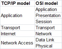
As
you can see, the TCP/IP model has fewer layers than the OSI model. The
Application, Presentation, and Session layers of the OSI model are
merged in only one layer, Application layer, in the TCP/IP model. Also,
Physical and Data Link layers are called Network Access layer in the
TCP/IP model.
Differences between OSI and TCP/IP modelThere are some other differences between these two models, besides the obvious difference in the number of layers. OSI model prescribes the steps needed to transfer data over a network and it is very specific in it, defining which protocol is used at each layer and how. The TCP/IP model is not that specific. It can be said that the OSI model prescribes and TCP/IP model describes.


